China Investment Casting Manufacturer
Investment Casting Portal: Home » Products »
Superalloy investment casting
» blades and vanes for industrial gas turbine
» turbine blade
Products Catagories
News & Events
-
Cold barrier (insufficient p...
[2021-6-15 11:43:31]Defect characteristics: the appearance of the casting is incomplete, there are crack-like gaps or cut-offs, and the metal edges at the cracks or cut-o...
-
Application of Urea Core in ...
[2021-6-8 15:46:58]Our factory successfully used urea cores to make complex internal cavity parts...
-
The Investment Casting Marke...
[2021-6-3 8:45:01]The Investment Casting Market is poised to register a CAGR of 4.58% over the forecast period 2020 - 2025...
-
Dynamic balance...
[2021-5-28 9:31:15]Dynamic balance...
-
Lost foam casting...
[2021-5-26 9:46:21]Lost foam casting...
Contact Information
TAIYUAN SIMIS INVESTMENT CASTING CO.,LTD
Add: Taiyuan City, Shanxi, China
Tel.: 0086-351-4063773
Mobile/Wechat/whatapp:18635108523
E-mail: market@investment-casting.biz
Web: http://www.investment-casting.biz

Products
turbine blade
 |

Previous:
blades and vanes for industrial gas turbine
Next:
turbine wheel
Model:
Description:
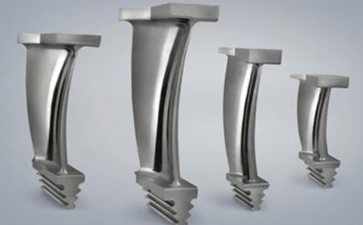
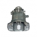
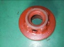
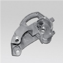
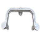
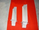
turbine blade
turbine blade, nozzle guide vane are our main vacuum investment castings. The material of those turbine blade made by SIMIS is nickel-based superalloy at present. In terms of the features of those investment casts, they have to be casted through vacuum furnace.
The length of our smallest turbine blade is 40mm and the thinnest thickness can be 0.5mm; the length of the largest one is about 500mm and the weight can be 13kg.
Equipped with vacuum furnaces, vacuum quenching furnace and fluorescence detection , and so on, SIMIS can produce most kinds of blades with the superalloy material used in gas turbine and nozzle.
A turbine blade is the individual component which makes up the turbine section of a gas turbine. The blades are responsible for extracting energy from the high temperature, high pressure gas produced by the combustor. The turbine blades are often the limiting component of gas turbines. To survive in this difficult environment, turbine blades often use exotic materials like superalloys and many different methods of cooling, such as internal air channels, boundary layer cooling, and thermal barrier coatings.
Blades of wind turbines and water turbines are designed to operate in different conditions, which typically involve lower rotational speeds and temperatures.
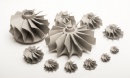
In a gas turbine engine, a single turbine section is made up of a disk or hub that holds many turbine blades. That turbine section is connected to a compressor section via a shaft (or "spool"), and that compressor section can either be axial or centrifugal. Air is compressed, raising the pressure and temperature, through the compressor stages of the engine. The temperature is then greatly increased by combustion of fuel inside the combustor, which sits between the compressor stages and the turbine stages. The high temperature and high pressure exhaust gases then pass through the turbine stages. The turbine stages extract energy from this flow, lowering the pressure and temperature of the air and transfer the kinetic energy to the compressor stages along the spool. This process is very similar to how an axial compressor works, only in reverse.
The number of turbine stages varies in different types of engines, with high bypass ratio engines tending to have the most turbine stages. The number of turbine stages can have a great effect on how the turbine blades are designed for each stage. Many gas turbine engines are twin spool designs, meaning that there is a high pressure spool and a low pressure spool. Other gas turbines use three spools, adding an intermediate pressure spool between the high and low pressure spool. The high pressure turbine is exposed to the hottest, highest pressure air, and the low pressure turbine is subjected to cooler, lower pressure air. The difference in conditions leads to the design of high pressure and low pressure turbine blades that are significantly different in material and cooling choices even though the aerodynamic and thermodynamic principles are the same.
turbine blades are subjected to very strenuous environments inside a gas turbine. They face high temperatures, high stresses, and a potential environment of high vibration. All three of these factors can lead to blade failures, potentially destroying the engine, therefore turbine blades are carefully designed to resist these conditions.
turbine blades are subjected to stress from centrifugal force (turbine stages can rotate at tens of thousands of revolutions per minute (RPM)) and fluid forces that can cause fracture, yielding, or creep failures. Additionally, the first stage (the stage directly following the combustor) of a modern turbine faces temperatures around 2,500 °F (1,370 °C) up from temperatures around 1,500 °F (820 °C) in early gas turbines. Modern military jet engines, like the Snecma M88, can see turbine temperatures of 2,900 °F (1,590 °C). Those high temperatures weaken the blades and make them more susceptible to creep failures. The high temperatures can also make the blades susceptible to corrosion failures. Finally, vibrations from the engine and the turbine itself) can cause fatigue failures.
A key limiting factor in early jet engines was the performance of the materials available for the hot section (combustor and turbine) of the engine. The need for better materials spurred much research in the field of alloys and manufacturing techniques, and that research resulted in a long list of new materials and methods that make modern gas turbines possible
The development of superalloys in the 1940s and new processing methods such as vacuum induction melting in the 1950s greatly increased the temperature capability of turbine blades. Further processing methods like hot isostatic pressingimproved the alloys used for turbine blades and increased turbine blade performance. Modern turbine blades often use nickel-based superalloys that incorporate chromium, cobalt, and rhenium.
Aside from alloy improvements, a major breakthrough was the development of directional solidification(DS) and single crystal (SC) production methods. These methods help greatly increase strength against fatigue and creep by aligning grain boundaries in one direction (DS) or by eliminating grain boundaries all together (SC).
Most turbine blades are manufactured by investment casting (or lost-wax casting processing). This process involves making a precise negative die of the blade shape that is filled with wax to form the blade shape. If the blade is hollow (i.e., it has internal cooling passages), a ceramic core in the shape of the passage is inserted into the middle. The wax blade is coated with a heat-resistant material to make a shell, and then that shell is filled with the blade alloy. This step can be more complicated for DS or SC materials, but the process is similar. If there is a ceramic core in the middle of the blade, it is dissolved in a solution that leaves the blade hollow. The blades are coated with the TBC they will have, and then cooling holes are machined as needed, creating a complete turbine blade.
IN-738GE used IN-738 as a first stage blade material from 1971 until 1984, when it was replaced by GTD-111. It is now used as a second stage material. It was specifically designed for land-based turbines rather than aircraft gas turbines.
Related Product
Hot Product

Didn't find what you are looking for? Send your inquiry.
turbine blade Manufacturer search on: Google, Yahoo, Msn
turbine blade Manufacturer search on: Google, Yahoo, Msn
Related Category:
Superalloy investment casting
» blades and vanes for industrial gas turbine
»
Simis China Investment Casting factory,a professional investment casting manufacturer through lost wax casting process in China.
Friendly Links: